Scans
Perhaps the most used type of macro is the scan macros. In general terms, we call scan to a macro that moves one or more motors and acquires data along the path of the motor(s).
Note
Sardana provides a Scan Framework for developing scan macros so that the scan macros behave in a consistent way. Unless otherwise specified, the following discussion applies to scan macros based on such framework.
The various scan macros mostly differ in how many motors are moved and the definition of their paths.
Typically, the selection of which data is going to be acquired depends on the active measurement group and is not fixed by the macro itself (although there is no limitation in this sense).
Depending on whether the motors are stopped before acquiring the data or not, we can classify the scan macros in step scans or continuous scans, respectively.
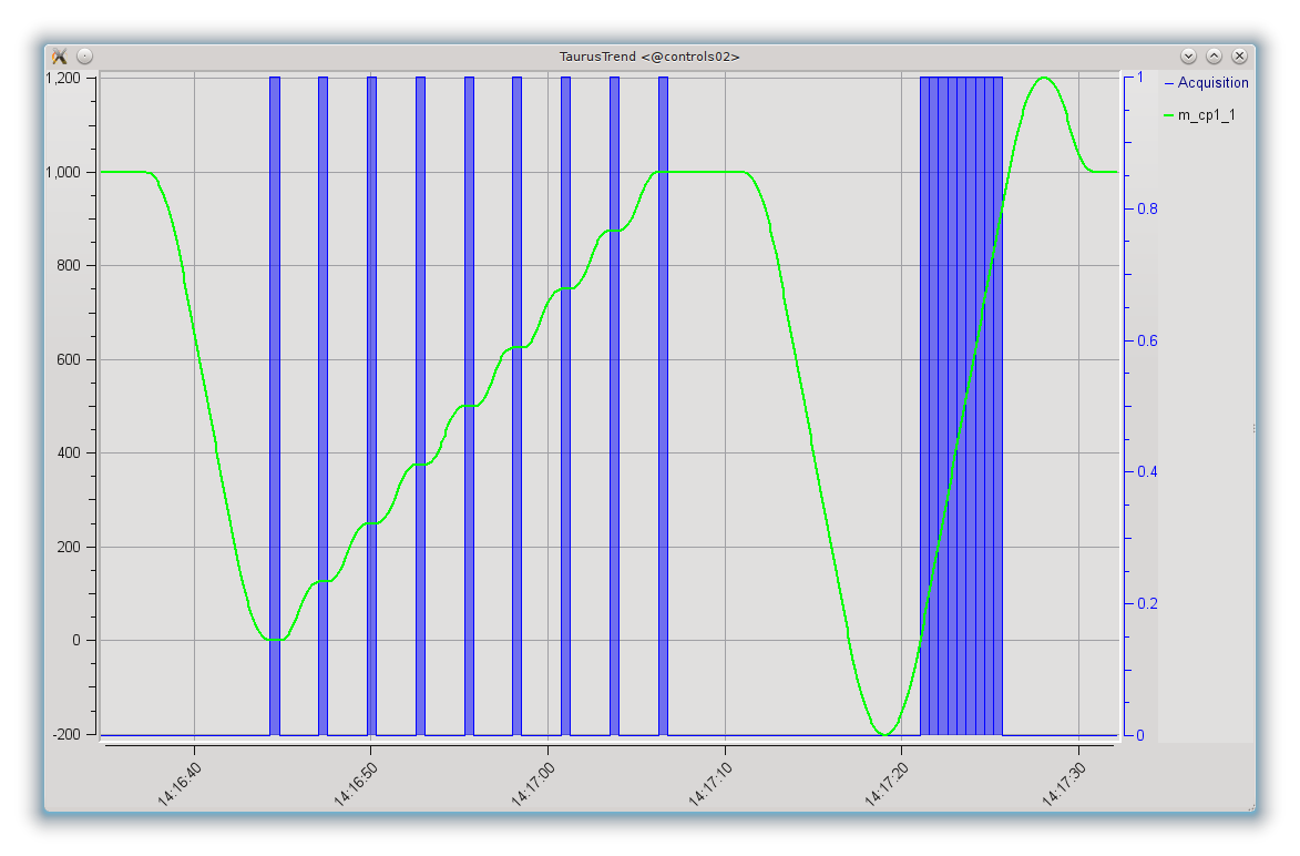
Trend plot showing a step scan (ascan m_cp1_1 0 1000 8 .5)
followed by a continuous scan (ascanc m_cp1_1 0 1000 .5).
The line corresponds to the motor position and the blue shaded areas
correspond to the intervals in which the data acquisition took place.
Step scans
In a step scan, the motors are moved to given points, and once they reach each point they stop. Then, one or more channels are acquired for a certain amount of time, and only when the data acquisition is finished, the motors proceed to the next point.
In this way, the position associated to a data readout is well known and does not change during the acquisition time.
Some examples of step scan macros are:
ascan,
a2scan, …
dscan,
d2scan, …
mesh.
A condition (implemented as a macro set in the environment
GeneralCondition) can be evaluated after each scan point.
In case the return value is True, the point will be repeated.
Continuous scans
In a continuous scan, the motors are not stopped for acquisition, which therefore takes place while the motors are moving. The most common reason for using this type of scan is optimizing the acquisition time by not having to wait for motors to accelerate and decelerate between acquisitions.
The continuous scans introduce some constraints and issues that should be considered.
If a continuous scan involves moving more than one motor simultaneously (as it is done, e.g. in
a2scan), then the movements of the motors should be synchronized so that they all start their path at the same time and finish it at the same time.If motors do not maintain a constant velocity along the path of their movement, the trajectories followed when using more than one motor may not be linear.
While in step scans it is possible to scan two pseudo-motors that access the same physical motors (e.g. the gap and offset of a slit, being both pseudo-motors accessing the same physical motors attached to each blade of the slit), in a continuous scan the motions cannot be decoupled in a synchronized way.
Backslash correction is incompatible with continuous scans, so you should keep in mind that continuous scans should only be done in the backslash-free direction of the motor (typically, by convention the positive one for a physical motor).
In order to address the first two issues, the scan framework attempts the following:
If the motors support changing their velocity, Sardana will adjust the velocities of the motors so that they all start and finish the required path simultaneously. For motors that specify a range of allowed velocities, this range will be used (for motors that do not specify a maximum allowed velocity, the current “top velocity” will be assumed to be the maximum)
For motors that can maintain a constant velocity after an acceleration phase (this is the case for most physical motors), Sardana will transparently extend the user-given path both at the beginning and the end in order to allow for the motors to move at constant velocity along all the user defined path (i.e., the motors are allowed time and room to accelerate before reaching the start of the path and to decelerate after the end of the nominal path selected by the user)
These two actions can be seen in the following plot of the positions of the two
motors involved in a a2scanc.
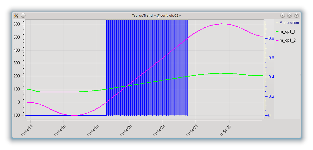
Trend plot showing a two-motor continuous scan
(a2scanc m_cp1_1 100 200 m_cp1_2 0 500 .1).
The lines correspond to the motor positions and the blue shaded areas correspond to the intervals in
which the data acquisition took place.
Both motors are capable of same velocity and acceleration, but since the required scan path for m_cp1_1 is shorter than that for m_cp1_2, its top velocity has been adjusted (gentler slope for m_cp1_1) so that both motors go through the user-requested start and stop positions simultaneously.
The same figure also shows how the paths for both motors have been automatically (and transparently, for the user) extended to guarantee that the user defined path is followed at constant velocity and that the data acquisition takes place also while the motors are running at constant velocity.
The synchronization of movement and acquisition can be done via hardware or via software. Currently Sardana provides two different interfaces for continuous scans. They can be easily differentiated by the scan name suffix:
c - allows only software synchronization
ct - allows both software and hardware synchronization (introduced with SEP6)
In the c type of scans, in order to optimize the acquisition time, Sardana
attempts to perform as many acquisitions as allowed during the scan time. Due
to the uncertainty in the delay times involved, it is not possible to know
beforehand how many acquisitions will be completed. In other words, the number
of acquired points along a continuous scan is not fixed (but it is guaranteed
to be as large as possible). Some examples of continuous scan macros are:
ascanc,
a2scanc, …
dscanc,
d2scanc, …
meshc.
In the ct type of scans, Sardana perform the exact number of acquisitions
selected by the user by the means of hardware or software synchronization
configurable on the
measurement group level.
The software synchronized channels may not follow the synchronization pace and
some acquisitions may need to be skipped. In order to mitigate this risk an
extra latency time can be spend in between the scan points. Another possibility
is to enable data interpolation in order to fill the gaps in the scan records.
Some examples of continuous scan macros are:
ascanct,
a2scanct, …
dscanct,
d2scanct, …
Currently he ct types of continuous scans still do not support acquiring of
external attributes e.g. Tango, however it is planned to support it in the
future.
Number of scan points in ct type of continuous scans indirectly depends
on the nr_interv macro parameter. If passed as a positive number, then the
scan will have nr_interv + 1 scan points (at the start and end of each interval),
but if passed as a negative number then the the scan will have one point less
(the point corresponding to the end of the last interval won’t be acquired).
This affects the scan motion range - when the last point is acquired
then the motion range is extended in order to acquire the last point at constant speed.
The following two sketches depicts this difference:
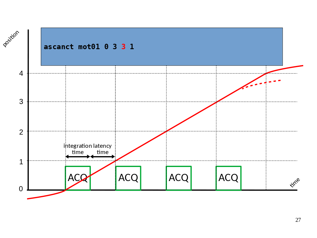
Motion and acquisition of continuous scan when nr_interv > 0.
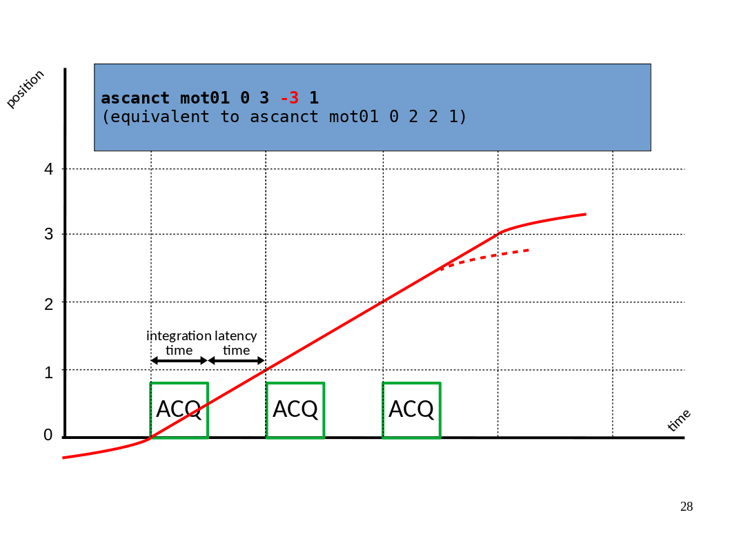
Motion and acquisition of continuous scan when nr_interv < 0.
On the above sketches, the dashed line indicates when theoretically the motion
could already start decelerating as it was foreseen in SEP6. However currently
deceleration starts after the last latency_time interval.
Note
The creation of two different types of continuous scans is just the result of the iterative development of the Scan Framework. Ideally they will merge into one based on the ct approach. This process may require backwards incompatible changes (up to and including removal of the affected scan macros) if deemed necessary by the core developers.
Configuration
Scans are highly configurable using the environment variables (on how to use environment variables see environment related macros in Standard macro catalog).
See also
For further information about the available Sardana Environment Variables, check the Environment Variable Catalog
Data storage
Data being produced by scans can be optionally handled by recorders and
sent to a variety of destinations. Typical use case is to store the scan data
in a file. To enable scan storage please refer to
Storage tab in Experiment Configuration UI,
newfile macro,
or environment variables.
Recorder types
Sardana defines some standard recorders e.g. the Spock output recorder or the
SPEC file recorder. From the other hand users may define their custom
recorders. Available recorders and recorder libraries can be displayed using
the lsrec and
lsreclib macros.
Sardana defines the following recorder types and comes with some built-in
recorders:
- file [*]
FIO_FileRecorder
NXscanH5_FileRecorder
SPEC_FileRecorder
- shared memory
SPSRecorder
ShmRecorder
- output
JsonRecorder
OutputRecorder
generic
[*] file recorders may either append new scans into the same file or dynamically create a new file or directory per scan using the information from the ScanID environment variable (see ScanDir and ScanFile environment variables on how to configure it).
NXscanH5_FileRecorder
NXscanH5_FileRecorder is a scan recorder which writes the scan data according to the NXscan NeXus application definition in the HDF5 file format.
Sardana scan recorders are instantiated per scan execution and therefore this recorder opens and closes the HDF5 file for writing when the scan starts and ends respectively. This may cause file locking issues with reading applications opened in between the scans. To overcome this issue the write session concept, with optional support of SWMR mode, was introduced for this particular recorder.
The write sessions use case scenarios:
- Manual session control with macros
To start and end the session you can use
h5_start_session/h5_start_session_pathandh5_end_session/h5_end_session_pathmacros. You can list the active sessions withh5_ls_sessionmacro.
- Programmatic session control with context manager (for macro developers)
You can use the
h5_write_sessioncontext manager to ensure that the write session is only active over a specific part of your macro code.
Scan snapshots
Snapshots are used for saving data (or metadata) from elements and devices not necessarily related to the scan itself. A scan saves only the values of the involved elements, that is positions of motors being moved, and values read from experiment channels in the active measurement group. If you want your scans to include something more you can use the snapshot.
Snapshot group can be configured via Experiment Configuration widget and PreScanSnapshot environment variable. It can include both Sardana elements as well as external (Tango) data sources.
The snapshot is saved only once during a scan, on the very beginning. The exact way the snapshot data is saved depends on the recorder and scan file format being used.
Scan statistics
Sardana may automatically calculate some basic statistics over the scan results e.g., max, mean, FWHM, etc.
In order to enable the automatic statistics calculation you just need to attach
the scanstats macro to the
post-scan hook place (see hook documentation
for more info). You can also do it on demand by directly executing
scanstats after executing the
scan macro.
Apart from printing the statistics by the scanstats macro these are stored in the door’s ScanStats environment variable. This way some other macro can use them e.g.,