Synchronization
When data is acquired while something else is changing — most prominently in continuous scans — each acquisition must happen at a well defined moment or place. Sardana models this with a dedicated synchronization layer: the measurement group describes when acquisitions should happen, and a synchronizer — either a software object inside the Pool or a hardware trigger/gate element — produces the corresponding signals which drive the experimental channels.
Synchronization domains
A synchronization event can be specified in two domains (see
SynchDomain):
- Time domain
The synchronizer is configured in time units (seconds) and the generation of the synchronization signals is based on passing time. This is the only domain available to software synchronizers.
- Position domain
The synchronizer is configured in distance units of a moveable element acting as the feedback source (mm, mrad, degrees, etc.) and the generation of the synchronization signals is based on receiving position updates from that source — typically an encoder signal processed by hardware such as motion controllers (e.g. IcePAP, Pmac) or versatile controllers (e.g. PandABox, PiLC). Synchronizing in the position domain makes the acquisition immune to velocity irregularities of the scanned motor: data is taken where the motor actually is, not where it is supposed to be at a given time.
A third domain, monitor (synchronization on acquired counts), is foreseen in the code but not used at the moment.
The measurement group describes the whole synchronization as groups of
equidistant acquisition intervals, each group characterized by parameters
like the initial point, delay, total and active intervals and the number of
repeats (see SynchParam and the
synchronization description).
Parameters may be expressed in either or both domains; when a parameter is
available in both, hardware capable of position synchronization may use the
position value while software synchronizers fall back to time.
Software versus hardware synchronization
The same synchronization description can be executed by two kinds of synchronizers:
- Software synchronization
A software object in the Pool generates the synchronization events and commands the channels to start (or start and stop) each acquisition. No extra hardware or cabling is required, but the precision is limited by the software stack: software synchronized channels may not follow the pace and acquisitions may need to be skipped, which is why continuous scans allow an extra latency time between points and optional data interpolation (see Continuous scans).
- Hardware synchronization
A trigger/gate element, interfaced via a
TriggerGateControllerplug-in, drives the experimental channels electrically. This provides deterministic timing, supports the position domain, and scales to fast acquisitions where software simply cannot keep up. The price is the need for real synchronization hardware, cabling and a controller plug-in (see How to write a trigger/gate controller).
Both modes are configured at the measurement group level: by default channels are synchronized by software; assigning a trigger/gate as the synchronizer of a timerable controller switches it to hardware synchronization.
Synchronization types
Independently of who generates the signal, the type of synchronization
(see AcqSynchType) determines how much of each
acquisition is controlled by the synchronizer:
- Trigger
The synchronizer starts each acquisition; the experimental channel decides on itself when to end, based on the integration time / monitor count.
- Gate
The synchronizer starts and ends each acquisition: the channel acquires for as long as the gate signal is active.
- Start
The synchronizer starts only the first acquisition; the experimental channel then drives the whole sequence itself, based on the integration time, latency time and number of repetitions.
Combining the synchronization type with its software or hardware nature
gives the modes Sardana actually uses during acquisition (see
AcqSynch). The following sketches illustrate them
(the upper line represents the synchronization signals, the lower line the
acquisition intervals of the channel):
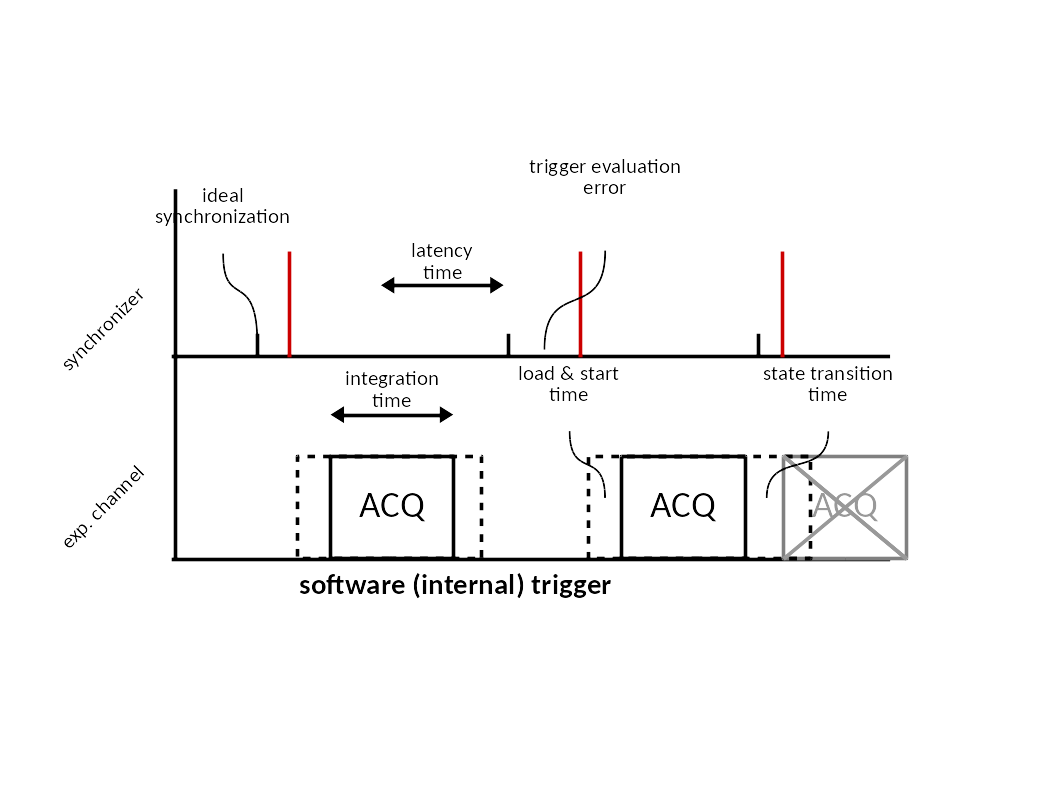
Software trigger - an internal (software) event starts each acquisition; the channel times its own integration.
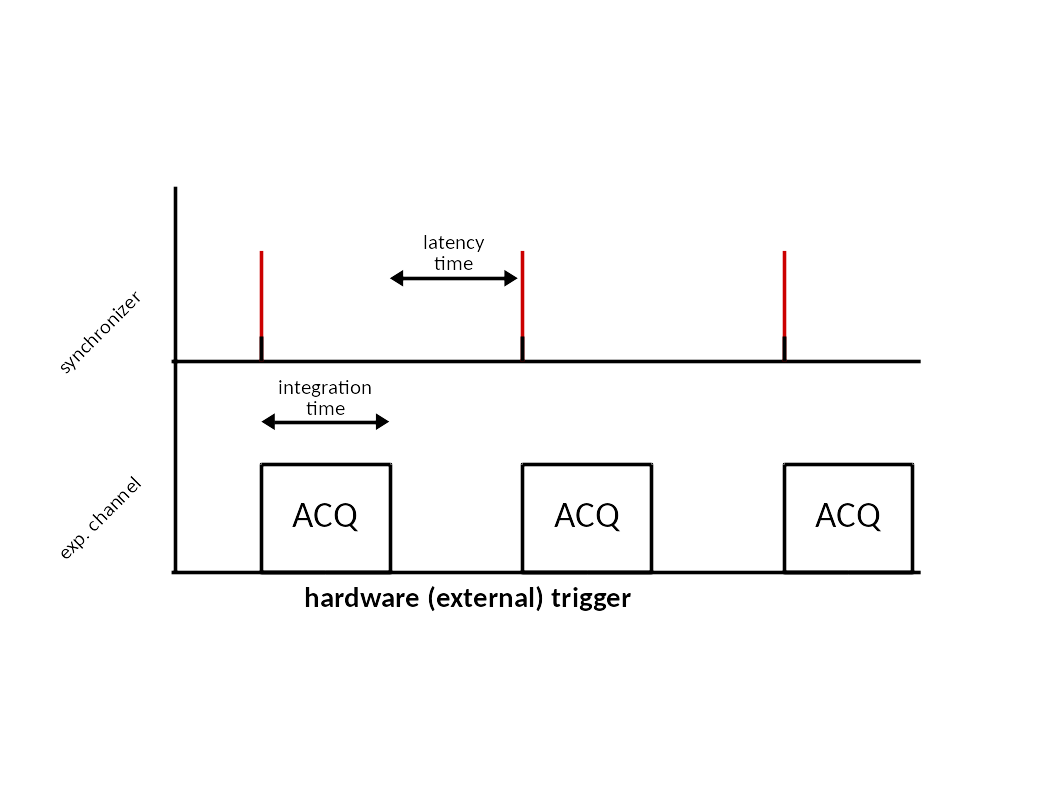
Hardware trigger - an external (hardware) pulse starts each acquisition; the channel times its own integration.
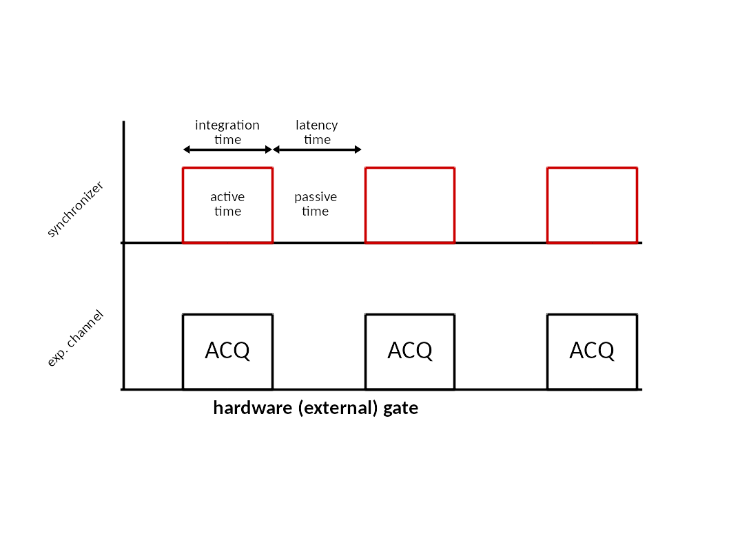
Hardware gate - an external (hardware) signal defines both the start and the duration of each acquisition.
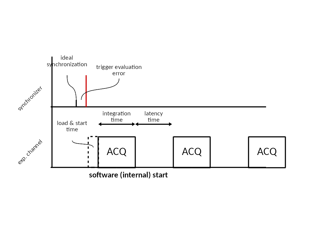
Software start - an internal (software) event starts only the first acquisition; the channel drives the following repetitions itself.
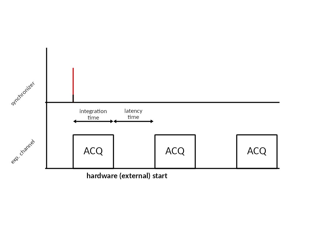
Hardware start - an external (hardware) pulse starts only the first acquisition; the channel drives the following repetitions itself.
A software gate mode is defined in the code but not implemented.
Trigger/gate elements in continuous scans
In a hardware synchronized continuous scan (ct scans), the scan framework
translates the user parameters (start, end, number of intervals, integration
time) into a synchronization description on the measurement group. During
the acquisition preparation the measurement group configures the
trigger/gate elements with this description; for the position domain, the
trigger/gate element must know which moveable’s encoder is connected to
which of its inputs (its MoveableOnInput attribute, see the
trigger/gate API). When several hardware
synchronizers are involved, their start order and parent-child relations can
be described by the measurement group start trigger tree (see
Configuration). During the scan the
synchronizer then produces the trigger or gate signals which clock the
hardware synchronized channels, while any software synchronized channels in
the same measurement group follow the equivalent software events.
See also
- Continuous scans
the continuous scan mechanics (velocity adjustment, path extension, latency time)
- Trigger/gate
the trigger/gate element
- Synchronization description
how trigger/gate controllers receive the synchronization description