Pool elements
This chapter describes the different element types managed by the Device Pool. Each element type defines a hardware independent interface; the actual hardware access is delegated to the element’s controller.
Motor
The motor is one of the most used elements in sardana. A motor represents anything that can be changed (and can potentially take some time to do it), so, not only physical motors (like stepper motors) fit into this category but also, for example, a power supply for which the electrical current can be modified. As it happens with the motor controller hardware and its physical motor(s), a sardana motor is always associated with its sardana motor controller.
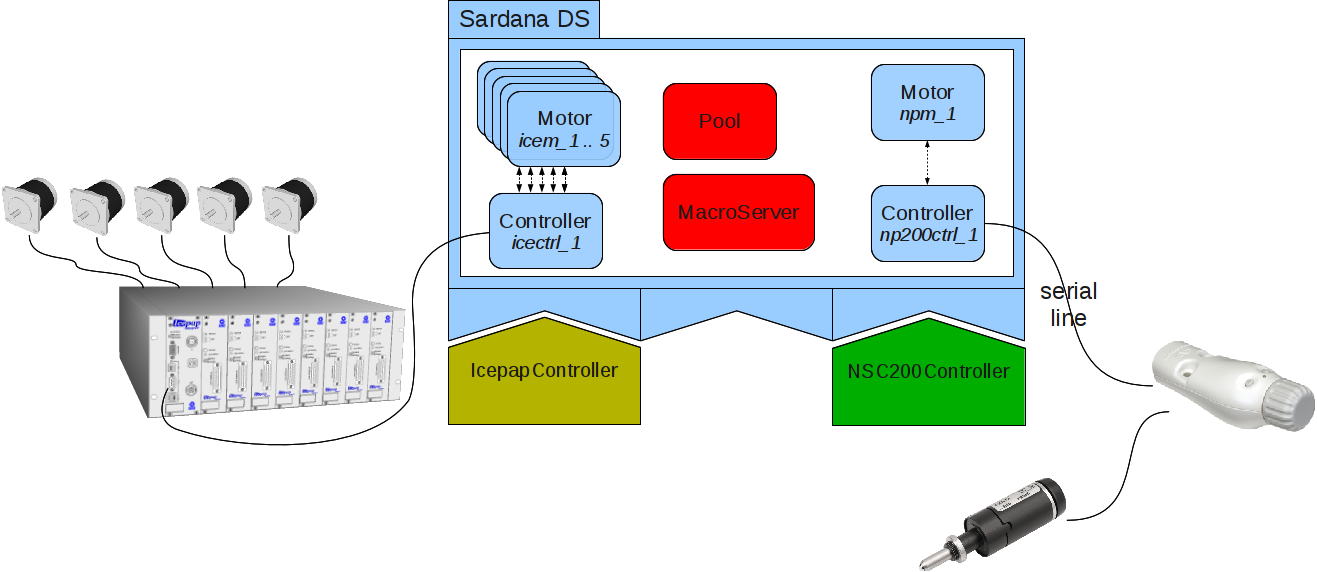
A diagram representing a sardana server with several motor controllers and their respective motors.
The motor object is also exposed as a Tango device.
See also
- Motor API reference
the motor API
Motorthe motor tango device API
Motor group
Whenever a move with more than one motor (or moveable element in general) is requested, a MotorGroup object containing all elements involved in the movement is silently created.
The motor group will not be removed automatically after the operation
finishes. This allows reuse of the groups by subsequent operations involving
the same set of moveables, but only within a given server run: on startup a
Pool or Sardana server removes the MotorGroup Tango devices
registered under its own instance. This cleanup may be disabled with the
CLEANUP_MOTOR_GROUPS sardana custom setting. You can however freely remove them manually with no
adverse effects.
The motor group object is also exposed as a Tango device, by default using
the mg/<pool name>/_mg_ms_<pid>_<num> name where pool name is
the alias or instance name of the Pool hosting the MotorGroup, pid is
a PID of the MacroServer that created the MotorGroup, and num is just
a sequential counter.
See also
MotorGroupthe motor group tango device API
PoolMotorGroupthe motor group internal class API
Pseudo motor
The pseudo motor interface acts like an abstraction layer for a motor or a set of motors allowing the user to control the experiment by means of an interface which is more meaningful to him(her).
One of the most basic examples is the control of a slit. The slit has two
blades with one motor each. Usually the user doesn’t want to control the
experiment by directly handling these two motor positions since they have
little meaning from the experiment’s perspective. Instead, it would be more
useful for the user to control the experiment by means of changing the gap
and offset values. In the Slit
controller, pseudo motors gap and offset will provide the necessary
interface for controlling the experiment’s gap and offset values
respectively.
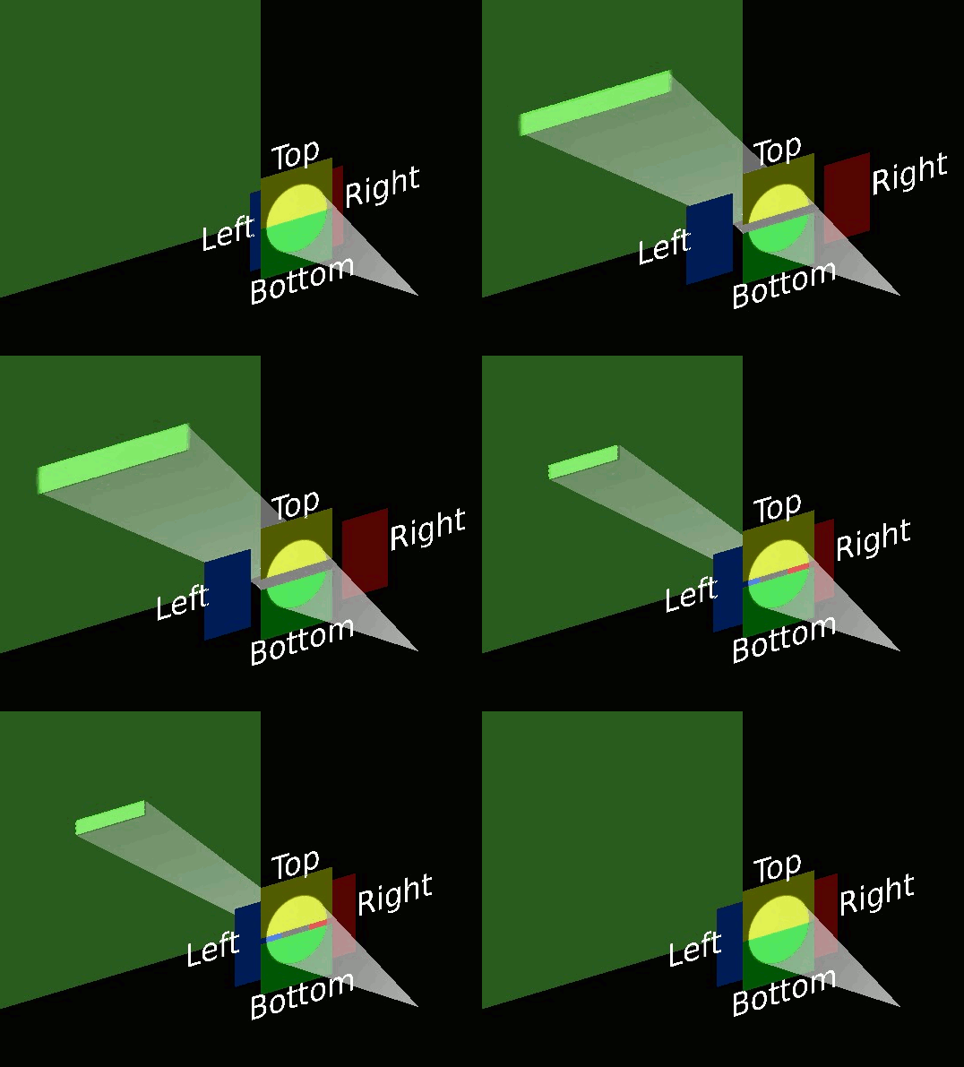
An animation [1] representing a system of slits composed from horizontal blades (left and right) and vertical blades (top and bottom).
In order to translate the motor positions into the pseudo motor positions and
vice versa, calculations have to be performed. The device pool provides the
PseudoMotorController class that can be
overwritten to provide new calculations.
The pseudo motor position gets updated automatically every time one of its motors position gets updated e.g. when the motion is in progress.
The pseudo motor object is also exposed as a Tango device.
See also
- Pseudo motor API reference
the pseudo motor API
PseudoMotorthe pseudo motor tango device API
I/O register
The IOR is a generic element which allows to write/read a value from a given
hardware register. This value type may be one of: int,
float, bool but the hardware usually expects a fixed type
for a given register.
In contrast to the writing of the motor’s position attribute, the writing of the IOR’s value attribute is an instant operation.
Note
Previously to adding Discrete Motion into Sardana the preferred way of implementing it was using TangoAttrIORController. However the IOR solution does not control the process of changing between the discrete positions. The discrete motion solution overcomes this limitation and should be used now.
The IOR has a very wide range of applications, for example it can serve to control the PLC registers.
See also
- I/O register API reference
the I/O register API
IORegisterthe I/O register tango device API
Counter/timer
The counter/timer is one of the most used elements in Sardana. A counter/timer represents an experimental channel which acquisition result is a scalar value. As its name indicates, it is foreseen to interface hardware counters or timers but it also fits well with other hardware like ADC or electrometers.
The acquisition operation on a counter/timer is executed over the integration time specified by the user. Counter/timer can be controlled by either software or hardware synchronization (Trigger/Gate) and multiple repetitions, also specified by the user, are possible within the same acquisition operation.
See also
- Counter/Timer API reference
the counter/timer API
CTExpChannelthe counter/timer tango device API
0D channel
The 0D experimental channel is used to access any kind of device which returns a scalar value and which is not a counter/timer. Very often (but not always), this is a commercial measurement equipment connected to a GPIB bus.
In order to have as precise as possible measurement, a dedicated acquisition operation is implemented for 0D channels. This operation will simply read the data from the hardware as fast as it can (only “sleeping” 10 ms between each reading) and a computation is done on the resulting data set to return only one value. Three types of computation are foreseen. The user selects which one he needs with an attribute.
The time during which this acquisition loop will get data is controlled by the counters/timers present in the measurement group - when all of them finish acquiring, the 0D acquisition operation will also stop.
See also
- 0D channel API reference
the 0D experiment channel API
ZeroDExpChannelthe 0D experiment channel tango device API
1D channel
The 1D represents an experimental channel which acquisition result is a spectrum value. It is foreseen to interface with MCA or position sensitive detectors.
The acquisition operation on a 1D channel is executed over the integration time specified by the user. 1D channels can be controlled by either software or hardware synchronization (Trigger/Gate) and multiple repetitions, also specified by the user, are possible within the same acquisition operation.
See also
- 1D channel API reference
the 1D experiment channel API
OneDExpChannelthe 1D experiment channel tango device API
2D channel
The 2D represents an experimental channel which acquisition result is an image value. It is foreseen to interface with CCD or photon-counting array detectors.
The acquisition operation on a 2D channel is executed over the integration time specified by the user. 2D channels can be controlled by either software or hardware synchronization (Trigger/Gate) and multiple repetitions, also specified by the user, are possible within the same acquisition operation.
See also
- 2D channel API reference
the 2D experiment channel API
TwoDExpChannelthe 2D experiment channel tango device API
Pseudo counter
Pseudo counter acts like an abstraction layer for an experimental channel (counter/timer, 0D, 1D or 2D) or a set of them allowing the user to see the experiment results by means of an interface which is more meaningful to him. Pseudo counters can be even built on top of other pseudo counters.
One example of a pseudo counter is
IoverI0 useful for normalizing the
measurement results in order to make them comparable.
In order to translate the experimental channel values into the pseudo
counter values, calculations have to be performed. The device pool provides
the PseudoCounterController class that can
be overwritten to provide new calculations.
The pseudo counter value gets updated automatically every time one of its experimental channel values gets updated e.g. when the acquisition is in progress.
Each pseudo counter is represented by a Tango device whose interface allows to obtain a calculation result (scalar value).
See also
- Pseudo counter API reference
the pseudo counter API
PseudoCounterthe pseudo counter tango device API
Measurement group
The measurement group interface allows the user to access several data acquisition channels at the same time. The measurement group is the key interface to be used when acquiring the data. The Pool can have several measurement groups and use them simultaneously. When creating a measurement group, the user composes it from:
external attribute e.g. Tango
It is not possible to have several times the same channel in a measurement group.
Configuration
In order to properly use the measurement group, each of the timerable controllers (Counter/Timer, 1D or 2D) needs to be assigned one of its channels as the timer or the monitor.
By default, the data acquisition channels are synchronized by software, meaning that the acquisition will be commanded to start (or start and stop) with the software precision. In order to achieve a better synchronization the hardware triggering (or gating) can be used by configuring a Trigger/Gate as the controller’s synchronizer. The synchronization concepts are explained in Synchronization.
The measurement group configuration can be modified with the expconf widget.
For each of the synchronization types: software or software start, the order of the timer/monitor channels in the expconf table determines which of them will act as the main one (will be started as the last one). The disabled channels do not count.
Start trigger tree
When hardware synchronizers are used, the measurement group may also define a
start trigger tree configuration. This tree describes the relations between
the synchronizers. In other words, it specifies which synchronizer starts
another synchronizer, and therefore determines the execution order of the
hardware synchronizers during the acquisition preparation. It is also used to
configure the
external start input
axis parameter of each synchronizer controller so that the child synchronizer
listens to the proper start signal coming from its parent synchronizer. You
can read or configure the start trigger tree with the following helper
macros: get_meas_start_trigger,
def_meas_start_trigger,
udef_meas_start_trigger.
See also
- Measurement group API reference
the measurement group API
MeasurementGroupthe measurement group tango device API
PoolMeasurementGroupthe measurement group class API
Trigger/gate
The trigger/gate represents synchronization devices like for example the digital trigger and/or gate generators. Their main role is to synchronize acquisition of the experimental channels.
Trigger or gate characteristics could be described in either the time and/or the position configuration domains. The role of trigger/gate elements in hardware synchronized acquisition, and the synchronization domains and types, are explained in Synchronization.
See also
- Trigger/Gate API reference
the trigger/gate API
TriggerGatethe trigger/gate tango device API
Footnotes